Fabric Discovery
The ACI fabric is brought up in a cascading manner, starting with the leaf nodes that are directly attached to the APIC. LLDP and control-plane IS-IS convergence occurs in parallel to this boot process. The ACI fabric uses LLDP- and DHCP-based fabric discovery to automatically discover the fabric switch nodes, assign the infrastructure VXLAN tunnel endpoint (VTEP) addresses.
APIC Cluster Connectivity

Erase Configuration
APIC Config Erase
To erase configuration of APIC so that we can re-setup APIC:
Sometimes KVM cannot launch because of Java issues. If you encounter such a problem, you can use Serial Over LAN as follows.
SSH to CIMC of the APIC:
ssh admin@<cimc IP addr>
Enable the Serial Over LAN (SoL):
cimc#
cimc# scope sol
cimc /sol # set enabled yes
cimc /sol *# set baud-rate 115200
cimc /sol *# commit
cimc /sol # connect host
CISCO Serial Over LAN:
Press Ctrl+x to Exit the session

Application Policy Infrastructure Controller
apic1 login: admin
Password:
Last login: Thu Mar 15 00:31:36 on tty1
apic# acidiag touch setup
apic# acidiag reboot
Switch Config Erase
To erase configuration of leaf/spine switch so that they can automatically retrieve configuration from APIC:
switch# acidiag touch clean
switch# reload
Fabric Initial Setup
Once the APIC is rebooted, it will start in the initial config wizard:
Starting Setup Utility


This setup utility will guide you through the basic configuration of
the system. Setup configures only enough connectivity for management
of the system.

*Note: setup is mainly used for configuring the system initially,
when no configuration is present. So setup always assumes system
defaults and not the current system configuration values.

Press Enter at anytime to assume the default values. Use ctrl-c
at anytime to restart from the beginning.


Cluster configuration ...
  Enter the fabric name [ACI Fabric1]: ACI Training
  Enter the fabric ID (1-128) [1]:
  Enter the number of controllers in the fabric (1-9) [3]:
  Enter the POD ID (1-9) [1]:
  Enter the controller ID (1-3) [1]:
  Enter the controller name [apic1]:
  Enter address pool for TEP addresses [10.0.0.0/16]:
  Note: The infra VLAN ID should not be used elsewhere in your environment
        and should not overlap with any other reserved VLANs on other platforms.
  Enter the VLAN ID for infra network (2-4094): 4094
  Enter address pool for BD multicast addresses (GIPO) [225.0.0.0/15]:

Out-of-band management configuration ...
  Enable IPv6 for Out of Band Mgmt Interface? [N]:
  Enter the IPv4 address [192.168.10.1/24]: 10.66.88.181/27
  Enter the IPv4 address of the default gateway [None]: 10.66.88.161
  Enter the interface speed/duplex mode [auto]:

admin user configuration ...
  Enable strong passwords? [Y]: N
  Enter the password for admin:

  Reenter the password for admin:

Cluster configuration ...
  Fabric name: ACI Fabric1
  Fabric ID: 1
  Number of controllers: 3
  Controller name: apic1
  POD ID: 1
  Controller ID: 1
  TEP address pool: 10.0.0.0/16
  Infra VLAN ID: 4094
  Multicast address pool: 225.0.0.0/15

Out-of-band management configuration ...
  Management IP address: 10.66.88.181/27
  Default gateway: 10.66.88.161
  Interface speed/duplex mode: auto

admin user configuration ...
  Strong Passwords: N
  User name: admin
  Password: ********

The above configuration will be applied ...

Warning: TEP address pool, Infra VLAN ID and Multicast address pool
         cannot be changed later, these are permanent until the
         fabric is wiped.

Would you like to edit the configuration? (y/n) [n]:n
Configuration Verification
Ensure the bond interace is up
Check which active interface is connected to the leaf:
apic1# cat /proc/net/bonding/bond0
Ethernet Channel Bonding Driver: v3.7.1 (April 27, 2011)

Bonding Mode: fault-tolerance (active-backup)
Primary Slave: None
Currently Active Slave: eth2-1 <<< Check the active interface
MII Status: up
MII Polling Interval (ms): 60
Up Delay (ms): 0
Down Delay (ms): 0

Slave Interface: eth2-1
MII Status: up <<< Ensure the bond member interface is up
Speed: 10000 Mbps
Duplex: full
Link Failure Count: 0
Permanent HW addr: d8:b1:90:61:30:74
Slave queue ID: 0

Slave Interface: eth2-2
MII Status: up <<< Ensure the bond member interface is up
Speed: 10000 Mbps
Duplex: full
Link Failure Count: 0
Permanent HW addr: d8:b1:90:61:30:75
Slave queue ID: 0
Ensure the lldp information is correct
Leaf switch discovers the attached APIC via LLDP and requests a TEP address via DHCP from the APIC.
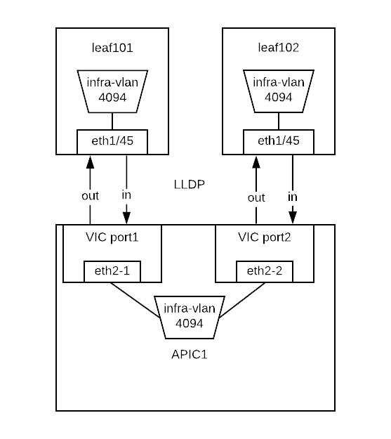
Check the incoming lldp information that APIC receives from Leaf switch:
apic1# acidiag run lldptool in eth2-1 | grep topo
  topology/pod-1/paths-101/pathep-[eth1/45]
  topology/pod-1/node-101

apic1# acidiag run lldptool in eth2-2 | grep topo
  topology/pod-1/paths-102/pathep-[eth1/45]
  topology/pod-1/node-102

apic1# acidiag run lldptool in eth2-1 | grep -A 1 -i vlan
Cisco Infra VLAN TLV
  4094

apic1# acidiag run lldptool in eth2-2 | grep -A 1 -i vlan
Cisco Infra VLAN TLV
  4094
Check the outgoing lldp information that APIC sends to Leaf switch:
apic1# acidiag run lldptool out eth2-1 | grep topo
  topology/pod-1/node-1

apic1# acidiag run lldptool out eth2-2 | grep topo
  topology/pod-1/node-1

apic1# acidiag run lldptool out eth2-1 | grep -A 1 -i vlan
Cisco Infra VLAN TLV
  4094

apic1# acidiag run lldptool out eth2-2 | grep -A 1 -i vlan
Cisco Infra VLAN TLV
  4094
Check the lldp neighbours on connected Leaf:
leaf101# show lldp neighbors
Capability codes:
  (R) Router, (B) Bridge, (T) Telephone, (C) DOCSIS Cable Device
  (W) WLAN Access Point, (P) Repeater, (S) Station, (O) Other
Device ID            Local Intf      Hold-time  Capability  Port ID
apic1                 Eth1/45         120                    eth2-1 <<< apic1 is a LLDP neighbor
spine201              Eth1/53         120        BR          Eth1/29
spine202              Eth1/54         120        BR          Eth1/29
Total entries displayed: 3
Ensure that the infra VLANs on APIC and Leaf match. If they do not match, please run the following to reset switch to manufacture config (bug CSCvd67346). Use prepare-mfg.sh on all switches in the environment and reload at the same time. For example:
leaf101# dir bootflash/
aci-n9000-dk9.12.1.2e.bin

leaf101# prepare-mfg.sh aci-n9000-dk9.12.1.2e.bin
If the incoming LLDP is empty (shown below), that means the VIC port has consumed the LLDP and the APIC port does not receive it. The reason is that the LLDP is enabled on VIC card. We need to disable the LLDP on the VIC card so that the LLDP information is passed to the APIC port (eth2-1).
 apic1# acidiag run lldptool in eth2-1

 apic1#

leaf101# show lldp neighbors
Capability codes:
  (R) Router, (B) Bridge, (T) Telephone, (C) DOCSIS Cable Device
  (W) WLAN Access Point, (P) Repeater, (S) Station, (O) Other
Device ID            Local Intf      Hold-time  Capability  Port ID
d8b1.9061.3071        Eth1/45         120                    d8b1.9061.3075  <<< The device is shown as mac address instead of APIC hostname.
spine201              Eth1/53         120        BR          Eth1/29
spine202              Eth1/54         120        BR          Eth1/29
Total entries displayed: 3
To disable LLDP on VIC, SSH as user admin to CIMC of the APIC:
CIMC# scope chassis
CIMC /chassis # show adapter
PCI Slot Product Name Serial Number Product ID Vendor
-------- -------------- -------------- -------------- --------------------
1 UCS VIC 1225 FCHxxxxxxxx UCSC-PCIE-C... Cisco Systems Inc
CIMC /chassis # scope adapter 1
CIMC /chassis/adapter # show detail | grep LLDP
LLDP: Enabled
CIMC /chassis/adapter # set lldp disabled
CIMC /chassis/adapter *# commit
New VNIC adapter settings will take effect upon the next server reset
CIMC /chassis/adapter # exit
CIMC /chassis # power cycle
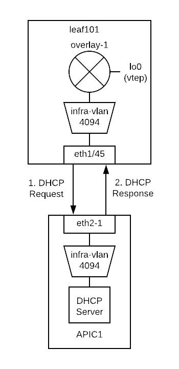
Ensure that the VTEP is assigned to the leaf switch
When leaf is registered, it will request VTEP address for loopback0 interface via DHCP.
leaf101# show ip interface brief vrf overlay-1
IP Interface Status for VRF "overlay-1"(4)
Interface            Address              Interface Status
eth1/49              unassigned           protocol-down/link-down/admin-up
eth1/50              unassigned           protocol-down/link-down/admin-up
eth1/51              unassigned           protocol-down/link-down/admin-up
eth1/52              unassigned           protocol-down/link-down/admin-up
eth1/53              unassigned           protocol-up/link-up/admin-up
eth1/53.2            unnumbered           protocol-up/link-up/admin-up
                     (lo0)
eth1/54              unassigned           protocol-up/link-up/admin-up
eth1/54.3            unnumbered           protocol-up/link-up/admin-up
                     (lo0)
vlan1                10.0.0.30/27         protocol-up/link-up/admin-up
lo0                  10.0.32.95/32        protocol-up/link-up/admin-up <<< VTEP
lo1023               10.0.0.32/32         protocol-up/link-up/admin-up
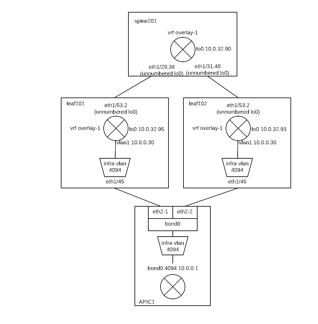
Once all switches are registered, we can see their VTEPs (loopback lo0 interfaces):
leaf101# acidiag fnvread
      ID   Pod ID                 Name    Serial Number         IP Address    Role        State   LastUpdMsgId
--------------------------------------------------------------------------------------------------------------
     101        1              leaf101      FDO20231J7L      10.0.32.95/32    leaf         active   0
     102        1              leaf102      SAL1946SWK8      10.0.32.93/32    leaf         active   0
     103        1              leaf103      SAL1946SWNT      10.0.32.92/32    leaf         active   0
     104        1              leaf104      SAL1946SWNU      10.0.32.91/32    leaf         active   0
     201        1             spine201                       10.0.32.90/32   spine         active   0
     202        1             spine202      SAL18391DXP      10.0.32.94/32   spine         active   0

Total 6 nodes
Also we can see the Dynamic Tunnel End Points are created in IS-IS:
leaf101# show isis dteps vrf overlay-1

IS-IS Dynamic Tunnel End Point (DTEP) database:
DTEP-Address       Role    Encapsulation   Type
10.0.64.64         SPINE   N/A             PHYSICAL,PROXY-ACAST-V4
10.0.64.65         SPINE   N/A             PHYSICAL,PROXY-ACAST-MAC
10.0.64.66         SPINE   N/A             PHYSICAL,PROXY-ACAST-V6
10.0.32.93         LEAF    N/A             PHYSICAL
10.0.32.92         LEAF    N/A             PHYSICAL
10.0.32.91         LEAF    N/A             PHYSICAL
10.0.32.90         SPINE   N/A             PHYSICAL
10.0.32.94         SPINE   N/A             PHYSICAL
The gateway of the APIC to reach other VTEPs is 10.0.0.30.
apic1# netstat -rn
Kernel IP routing table
Destination     Gateway         Genmask         Flags   MSS Window  irtt Iface
0.0.0.0         10.66.88.161    0.0.0.0         UG        0 0          0 oobmgmt
10.0.0.0        10.0.0.30       255.255.0.0     UG        0 0          0 bond0.4094
10.0.0.30       0.0.0.0         255.255.255.255 UH        0 0          0 bond0.4094
10.0.64.64      10.0.0.30       255.255.255.255 UGH       0 0          0 bond0.4094
10.0.64.65      10.0.0.30       255.255.255.255 UGH       0 0          0 bond0.4094
10.66.88.160    0.0.0.0         255.255.255.224 U         0 0          0 oobmgmt
169.254.1.0     0.0.0.0         255.255.255.0   U         0 0          0 teplo-1
169.254.254.0   0.0.0.0         255.255.255.0   U         0 0          0 lxcbr0
apic1#
Reference
- Disable LLDP on VIC https://supportforums.cisco.com/legacyfs/online/attachments/document/files/apic-vic-lldp-fn.pdf
- CNA Data Center DCICT 200-155 Official Cert Guide by Ahmed Afrose et. al.